
Start looking for a way to upload Sketches to the Arduino wirelessly.
After some Internet searching… decided to go deeper and understand how the HC-06 Bluetooth module works and how is the upload process.
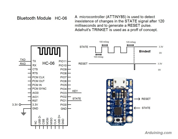
In the HC-06, the STATUS signal indicates when a Bluetooth bind condition is established.
After look at the signal, the first idea was to use an LM555 as a resettable monostable multivibrator… ok, an 8 pin DIP IC and several passive components….
Then why no use an ATTINY85 to do the work?
Here is the proof of concept using an Adafruit’s TRINKET 3.3V.
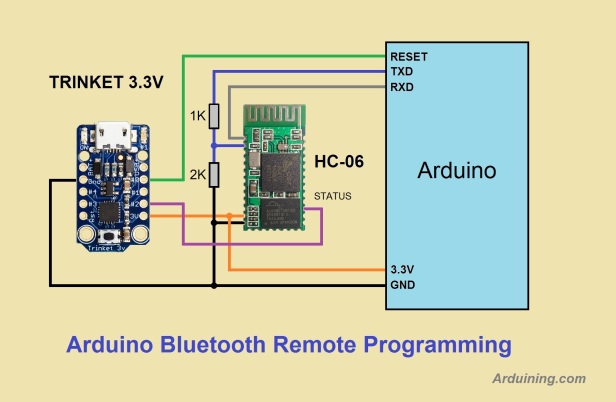
The TRIKET checks the behavior of the STATE signal to identify the bind condition and generates the RESET pulse.
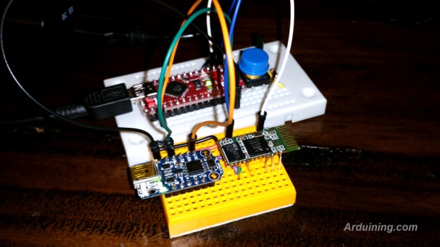
Test made with an Arduino NANO clone:
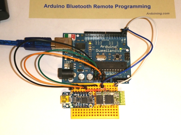
Testing Arduino Duemilanove (same HC-06 configuration, 57600 bauds):
The Sketch used in the TRINKET:
/*Trinket_BlueReset.ino   Arduining 4 OCT 2016
 Using TRINKET to generate the RESET for Remote Arduino Programming.

 -HC-06 BlueTooth Module as Slave 115200 bauds (UNO, Optiboot loader)
 -HC-06 BlueTooth Module as Slave 57600 bauds (Duemilanove, NANO)
 -Using the STATUS pin of The HC-06 to identify a Binded condition.
 -The TRINKET LED (pin 1) show the Bluetooth condition:
          5 Hz Not Binded, 1 Hz Binded.

 -STATPIN is the STATUS signal from HC-06 (pin 24).
 -RESETPIN is the RESET signal to start the bootloader in the Arduino.
             |<--200mSeg-->|             |<120mSeg>|
              ______        ______        _______________________________
   STATPIN __|      |______|      |______|
           --------------  Not Binded ------------>|<----- Binded -------
            _______________________________________ _____________________
   RESETPIN                                        |


  -If no changes in STATPIN for 120 milliseconds a RESETPIN pulse is generated.

                           __,-----,__
                          |[]|_____|[]|<===LED
   [----- (4.3-16)V ----->|o         o|[---- +USB(+5V 500mA) ---->
   <-------- GND -------->|o         o|<PB0>-<0>-[0A>-<SDA>-[MOSI>  ==> RESETPIN
   USB-<4A]-[A4>-<4>-<PB4>|o TRINKET o|<PB1>-<1>-[1A>-------<MISO]-LED>
   USB------[A3>-<3>-<PB3>|o         o|<PB2>-<2>-<A1]-[SCL>-[SCK >  <== STATPIN
   [-------- RESET------->|o         o|+3.3V(150mA)Reg. from BAT->
                          |   [( )] __|
                           \_______/
                  Trinket (3.3V) Pinout Diagram

 -----------------------------------------------------------------------------*/

#define LEDPIN     1               // LED PIN for signaling.
#define RESETPIN   0               // Attached to the RESET pin of the Arduino.
#define STATPIN    2               // Attached to the STATUS pin of the HC-06
volatile bool flag= false;
int pulseTimer= 120;               // Waiting time for pulses in STATPIN (mSeg)

/*------------------------------------------------------------------------------
  setup()
------------------------------------------------------------------------------*/
void setup(){
    GIMSK = 0b00100000;            // turns on pin change interrupts
//    PCMSK = 0b00010011;          // turn on interrupts on pins PB0, PB1, & PB4
    PCMSK = 0b00000100;            // turn on interrupts on pin 2 (PB2)
    sei();                         // enables interrupts

    pinMode(LEDPIN, OUTPUT);
    pinMode(RESETPIN, OUTPUT);
    pinMode(STATPIN, INPUT_PULLUP);
    digitalWrite(RESETPIN, HIGH);  // Set RESET to High.
}

/*------------------------------------------------------------------------------
  loop()
------------------------------------------------------------------------------*/
void loop(){
  delay(1);

	if(flag){
    pulseTimer=120;                // Reset waiting time for pulses in STATPIN.
    flag = false;
	}
  else pulseTimer--;

	if(pulseTimer == 0){
    //Here we can check for a '0' in the serial channel (57600 bauds).
	  digitalWrite(RESETPIN, LOW);   // Produce a RESET pulse of 1 millisecond.
    delay(1);
    digitalWrite(RESETPIN, HIGH);  // Return to High.

    while(!flag){
      digitalWrite(LEDPIN,LOW);
      delay(500);
      digitalWrite(LEDPIN,HIGH);
      delay(500);
      }                            // Hold until next Binding.
	}

}

/*------------------------------------------------------------------------------
  Pin Change Interrupt of pin 2 (PB2).
------------------------------------------------------------------------------*/
ISR(PCINT0_vect){
    flag = true;                   // signals the change in pin 2.
    digitalWrite(LEDPIN,digitalRead(STATPIN));   //Signaling the HC-06 STATUS.
    sei();                         // enables interrupts
}
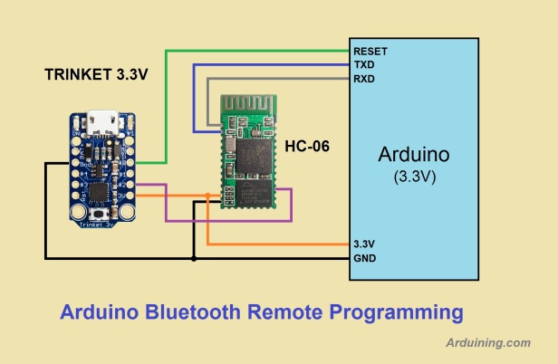
If the Arduino to be programmed works with 3.3V the wiring is simpler:
Now we can program the Arduino without the USB cable. Also we can control the robot remotely via Bluetooth, just remember to use Serial.begin(57600) in your control program ….
Any additional ideas will be appreciated,
Thanks for visiting this blog.
