
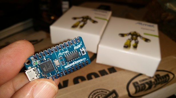
Atmel launches the ATtiny104 Xplained Nano evaluation kit, a nice way of introducing this $0.40 microcontroller.

The small and low cost evaluation board includes an on-board programmer.
After received two boards from Digikey, started downloading the Atmel Studio.
The Atmel Studio is a “BIG” tool and takes time for the installation, but after the waiting, everything went smooth.
I spent some time drawing the Pinout Diagram, it helps me to learn more about the mini development kit.

In no time the ATtiny104 was reading the PUSH BUTTON and controlling the on board LED.

Next thing to do: experimenting with the serial port.
The character ‘U’ is sent every 500 milliseconds if the BUTTON is pressed.
The working code transmitting at 9600 bauds:
/* ATTINY104_Serial.c
*  Created: 3/24/2016 08:20:00 PM
*  Author : Ardunaut
* Program to test serial transmission.
* While the BUTTON is pressed:
* 'U' character is transmitted every 500 milliseconds.
* The LED blinks when a char transmitted.
* FOSC=1000000 :"After powering up the device or after a reset the system clock is automatically
* set to calibrated internal 8MHz oscillator, divided by 8" (Datasheet pag.32)
* Using C functions from: http://www.atmel.com/Images/Atmel-42505-8-bit-AVR-Microcontroller-ATtiny102-ATtiny104_Datasheet.pdf
* Note: Zeros ('0') were removed from the register names to make the code compatible.
                 __________
           VCC--|1       14|--GND (TPI CLK)
           PA0--|2       13|--PB3 (CDC TX) -->USART_Transmit()
(TPI DATA) PA1--|3       12|--PB2 (CDC RX) <--USART_Receive()
   (RESET) PA2--|4       11|--PB1 (BUTTON)
           PA3--|5       10|--PB0
           PA4--|6        9|--PA7
     (LED) PA5--|7        8|--PA6
                \__________/
        Atmel ATtiny104 Xplained Nano
  */

#include <avr/io.h>
#include <util/delay.h>

#define LED_PIN    (1 << PA5)
#define BUTTON_PIN (1 << PB1)
#define FOSC 1000000
#define BAUD 9600
#define MYUBRR FOSC/16/BAUD   //adding or subtracting 1 may be necessary.

void PORTS_init(void){
  PUEB |= BUTTON_PIN;         // Enable Pull-Up function in PB1.
  PORTB |= BUTTON_PIN;        // Set Pull-Up for the Button.
  DDRA |= LED_PIN;            // Configure LED pin as Output.
}

void USART_Init( unsigned int ubrr)
{
  /*Set baud rate */
  UBRRH = (unsigned char)(ubrr>>8);
  UBRRL = (unsigned char)ubrr;
  /*Enable receiver and transmitter */
  UCSRB = (1<<RXEN)|(1<<TXEN);
  /* Set frame format: 8data, 2stop bit */
  UCSRC = (1<<USBS)|(3<<UCSZ0);
  _delay_ms(250);
  PORTA |= LED_PIN;         // Switch off the LED.
  }

void USART_Transmit( unsigned char data )
{
  /* Wait for empty transmit buffer */
  while ( !( UCSRA & (1<<UDRE)) );
  /* Put data into buffer, sends the data */
  UDR = data;
}

unsigned char USART_Receive( void )
{
  /* Wait for data to be received */
  while ( !(UCSRA & (1<<RXC)) );
  /* Get and return received data from buffer */
  return UDR;
}

void USART_Flush( void )
{
  unsigned char dummy;
  while ( UCSRA & (1<<RXC) ) dummy = UDR;
}

/*----------------------------------------------------------------------------------------------------------------------------------------------------------*/
void main( void ){
  PORTS_init();
  USART_Init(MYUBRR);

  while(1){
    while(PINB & BUTTON_PIN){}  // Wait until the Button is pressed.
    PORTA &= ~LED_PIN;          // Switch on the LED.
    USART_Transmit( 'U' );
//    USART_Transmit( 85 );
    _delay_ms(50);
    PORTA |= LED_PIN;           // Switch off the LED.
    _delay_ms(450);
  }
}
Some soldering to continue experimenting with the Xplained NANO in a breadboard.


Now, looking for an efficient code and low power solution to create an IoT node…
First, testing the hardware:
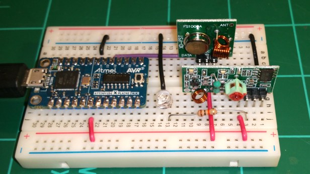
Transmitting at 300 bauds with the USART connected to the 433Mhz RF module:
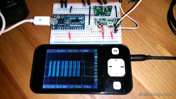
This is the code to transmit “HELLO” every second (while the button is pressed).
/* * ATTINY104_RF300.c
* -Using the USART for 300 bauds transmission with the RF Module (433Mhz).
* -Tree 0xAA bytes are sent as preamble of the message to balance the receptor.
* -While the BUTTON is pressed "HELLO" message is transmitted every second aprox.
* -Characters are separated 50 milliseconds (20 milliseconds of mark).
* -The LED is ON during the message is transmission.
* -FOSC= 1000000 : "After powering up the device or after a reset the system clock is automatically
*  set to calibrated internal 8MHz oscillator, divided by 8" (Datasheet pag.32)
* -Using C functions from: http://www.atmel.com/Images/Atmel-42505-8-bit-AVR-Microcontroller-ATtiny102-ATtiny104_Datasheet.pdf
* -Note: Zeros ('0') were removed from the register names to make the code compatible.
* -Created: 3/26/2016 07:25:00 PM
* -Author : Ardunaut
                 __________
           VCC--|1       14|--GND (TPI CLK)
           PA0--|2       13|--PB3 (CDC TX) -->USART_Transmit()
(TPI DATA) PA1--|3       12|--PB2 (CDC RX) <--USART_Receive()
   (RESET) PA2--|4       11|--PB1 (BUTTON)
           PA3--|5       10|--PB0
           PA4--|6        9|--PA7
     (LED) PA5--|7        8|--PA6
                \__________/
        Atmel ATtiny104 Xplained Nano
*/

#include <avr/io.h>
#include <util/delay.h>

#define LED_PIN    (1 << PA5)
#define BUTTON_PIN (1 << PB1)
#define FOSC 1000000 // Clock Speed
#define BAUD 300
#define MYUBRR FOSC/16/BAUD-1

void PORTS_init(void){
  PUEB |= BUTTON_PIN;         // Enable Pull-Up function in PB1.
  PORTB |= BUTTON_PIN;        // Set Pull-Up for the Button.
  DDRA |= LED_PIN;            // Configure LED pin as Output.
}

void USART_Init( unsigned int ubrr){
  //Set baud rate:
  UBRRH = (unsigned char)(ubrr>>8);
  UBRRL = (unsigned char)ubrr;
  //Enable receiver and transmitter:
  UCSRB = (1<<RXEN)|(1<<TXEN);
  // Set frame format: 8data, 2stop bit :
  UCSRC = (1<<USBS)|(3<<UCSZ0);
  _delay_ms(250);
  PORTA |= LED_PIN;         // Switch off the LED.
  }

void USART_Transmit( unsigned char data ){
  // Wait for empty transmit buffer:
  while ( !( UCSRA & (1<<UDRE)) );
  // Put data into buffer, sends the data:
  UDR = data;
}

unsigned char USART_Receive( void ){
  // Wait for data to be received:
  while ( !(UCSRA & (1<<RXC)) );
  // Get and return received data from buffer :
  return UDR;
}

void USART_Flush( void ){
  unsigned char dummy;
  while ( UCSRA & (1<<RXC) ) dummy = UDR;
}
/*----------------------------------------------------------------------------------------------------------------------------------------------------------*/
void main( void ){
  PORTS_init();
  USART_Init(MYUBRR);

  while(1){
    while(PINB & BUTTON_PIN){}  // Wait until the Button is pressed.
    PORTA &= ~LED_PIN;          // Switch on the LED.

    USART_Transmit( 0xAA );   // To balance the receptor.
    _delay_ms(50);
    USART_Transmit( 0xAA );   // To balance the receptor.
    _delay_ms(50);
    USART_Transmit( 0xAA );   // To balance the receptor.
    _delay_ms(50);
    USART_Transmit( 'H' );
    _delay_ms(50);
    USART_Transmit( 'E' );
    _delay_ms(50);
    USART_Transmit( 'L' );
    _delay_ms(50);
    USART_Transmit( 'L' );
    _delay_ms(50);
    USART_Transmit( 'O' );

    PORTA |= LED_PIN;         // Switch off the LED.
    _delay_ms(650);           // delay to complete one second.
  }
}
More experiments and learning …


testing….3GB Windows Software on hdd for programming 1KB atmel ? hi hi .. unusable…
Hi, and thank you for sharing with us. So I tried the second example with multiple characters being transmitted 50ms apart and the data appears to get corrupted when the baud rate is increased from 300 (in your example) to 9600. Do you have any ideas why?
Thanks.
The transmission rate limit is 10Khz but with a very distorted wave shape (rise and fall times are different). Asincronous serial may be not the best approach if you want to maximize the baudrate.
Roman Black did some work on TX routines for these cheapo modules; and managed to get reliable speeds and range; he was using PIC micro’s,but it should yield some useful ideas for other chip families too.
Roman Black did some work on these cheapo FR links with PIC micro’s; he managed (with some clever tricks) to get range, speed, and reliability! and all from the cheapest, crudest RF modules on the planet!
P.S had trouble logging in with wordpress,as my login details dated back to 2008…!
Did you also experiment with the receiving part? I can’t get that one to work so far…
Came across this site from a random google search, ostensibly so I could plug in the Nano as is into a target with minimal amendments to pin loading, especially when running a 31Amp 650V MOSFET on 339V DC rail on an isolated setup – of course only running when not plugged into USB 🙂 !
Difference is:-
Although tpidata, tpiclk, reset are the same on my ATtiny 140 Xplained Nano (circa 2022), the Rx, Tx have different pinout, as in swapped around:-
Atmega32U4 pin 6 CDC RX goes to ATtiny pin 12
Atmega32U4 pin 7 CDC TX goes to ATtiny pin 13
Also regardless of the mEDBG baud rate I don’t see any “U” characters though do see munted ASCII of sorts or when in hex 8 bit data with some bit 7’s set (on a small set of around 2400-9600 bauds) – this is using Microchip studio visualisation of the virtual com port when the Nano is plugged into the USB (Com port 6 comes up) maybe that’s just listening on the handshake through USB but, there is activity between the Atmega32U4 and the ATtiny104 Xplained Nano board – this is on a brand new unprogrammed Nano from Digi-Key in original packaging…
Comments welcome ?
Regards
Mike
Ah ha, I see what’s happened 😦
Attiny 104 pin 12 is a TxD output, the label adjacent to it on the xplained user guide shows cdc Rx which at first shows it as a receive but, that terminology just means it goes to the CDC Rx pin on the atmega32U4, similarly for attiny pin13, it is a RxD pin but, connects to the atmega32U4 TxD pin hence why CDC Tx is shown adjacent to the attiny 104.
Hrrrm, lines on a graphic would have been a bit clearer…
So, never mind in that respect.
Now however, I’m keen to ensure the atmega32U4 is tri state when control transferred to the attiny104 ie the 5 resistors suggested that could be unsoldered should hopefully only connect to tristated atmega32U4 lines, then all is good, testing continues.
PS can’t edit my last comment I meant attiny 104 not 140.
Cheers
Mike