
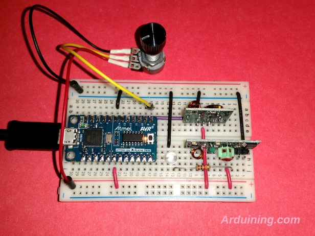
This is a working example of the analog acquisition made with the ATTINY104.
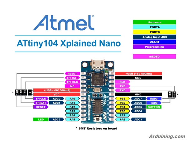
Pinout Diagram:
ATtiny104 Xplained NANO and Atmel Studio 7 was used.
Here is the C code:
/*ATtiny104_ADC_Serial.c
* Example of the DAC operation.
* A potentiometer is used to produce voltage variations at PA6 (ADC3),
* Analog value (upper 8 bits) is read and sent serially at 9600 bauds every 500 msecs.
* Created: 3/29/2016 10:30:00 PM
* Author : Ardunaut
                     ____________
               VCC--|1         14|--GND
  TPI CLK/ADC0 PA0--|2         13|--PB3 ADC7/CDC RX <--USART_Receive()
 TPI DATA/ADC1 PA1--|3         12|--PB2 ADC6/CDC TX -->USART_Transmit()
    (RESET)    PA2--|4         11|--PB1 ADC5/BUTTON
               PA3--|5         10|--PB0 ADC4
               PA4--|6          9|--PA7
      LED/ADC2 PA5--|7          8|--PA6 ADC3  <---- Potentiometer
                     \__________/
             Atmel ATtiny104 Xplained Nano
*/

#define F_CPU 1000000
#include <avr/io.h>
#include <util/delay.h>
#define LED_PIN    (1 << PA5)
#define BUTTON_PIN (1 << PB1)       // Not used in this example
#define BAUD 9600
#define MYUBRR F_CPU/16/BAUD        // +1, 0 or -1 to adjust the timming.

void PORTS_Init( void ){
  PUEB |= BUTTON_PIN;               // Enable Pull-Up function in PB1.
  PORTB |= BUTTON_PIN;              // Set Pull-Up for the Button.
  DDRA |= LED_PIN;                  // Configure LED pin as Output.
}

void USART_Init( unsigned int ubrr){  // Initialize USART
  UBRRH = (unsigned char)(ubrr>>8); // Set the baud rate
  UBRRL = (unsigned char)ubrr;
  UCSRB = (1<<RXEN)|(1<<TXEN);      // Enable Receiver and Transmitter
  UCSRC = (1<<USBS)|(3<<UCSZ0);     // Set Format: 8 data, 2 stop bit
}

void USART_Transmit( unsigned char data ){
  while ( !( UCSRA & (1<<UDRE)) );  // Wait for empty buffer.
  UDR = data;                       // Put data into buffer.
}

unsigned char USART_Receive( void ){
  while ( !(UCSRA & (1<<RXC)) );    // Wait for received data.
  return UDR;                       // Return received data.
}

void USART_Flush( void ){
  while ( UCSRA & (1<<RXC) ){};
}

void ADC_Init( void ){         // Initialize the ADC

 //Set Voltage reference as VCC and select channel ADC3 (PA6).
  ADMUX =
            (0 << REFS1) |     // VCC as V. reference, bit 1
            (0 << REFS0) |     // VCC as V. reference, bit 0
            (0 << MUX2)  |     // use ADC3 (PA6), MUX bit 2
            (1 << MUX1)  |     // use ADC3 (PA6), MUX bit 1
            (1 << MUX0);       // use ADC3 (PA6), MUX bit 0

  //Set prescaler to 64 for MCU running at 8MHz (125 ksasmples/sec)
  ADCSRA =
            (1 << ADEN)  |     // Enable ADC
            (1 << ADPS2) |     // Set prescaler=64 (125kHz), bit 2
            (1 << ADPS1) |     // Set prescaler=64 (125kHz), bit 1
            (0 << ADPS0);      // Set prescaler=64 (125kHz), bit 0

  // ADLAR is set to 1 (Left-shift result, bits ADC9..ADC2 in ADCH)
  ADCSRB =
          (1 << ADLAR);        // Left Adjustment for ADC Result Readout
}

//-----------------------------------------------------------------------------

int main( void ){
  PORTS_Init();
  USART_Init(MYUBRR);
  ADC_Init();
  uint8_t digit,data;

  while(1){
    ADCSRA |= (1 << ADSC);          // start ADC measurement
    while (ADCSRA & (1 << ADSC) );  // wait till conversion complete

    PORTA &= ~LED_PIN;              // Switch on the LED.
    data= ADCH;
    digit= data/100;
    USART_Transmit( '0'+digit );    // Transmit hundreds
    digit= (data % 100)/10;
    USART_Transmit( '0'+digit );    // Transmit tens
    digit= data % 10;
    USART_Transmit( '0'+digit );    // Transmit units
    USART_Transmit( 13 );           // Transmit Car Return
    USART_Transmit( 10 );           // Transmit Line Feed
    _delay_ms(50);
    PORTA |= LED_PIN;               // Switch off the LED.
    _delay_ms(450);                 // Delay before next data acquisition.
  }

}  // End of main.
…

Do you have the RX / TX pins mixed up? Datasheet says RxD0 is pin 13 and TxD0 is pin 12
Thanks Kevin, corrected.