
To plug the ESP-201 in the breadboard is necessary to remove the 4 pin connector from the botton of the board and install it in the component side.

A quick pinout reference to start the wiring:

Note: GPIO9 and GPIO10 are connected to the FLASH memory (may be unusable). Here is a “surgery” procedure to use them: ESP-201 board modification
First experiment sending the analog value from A0 to ThingSpeak:

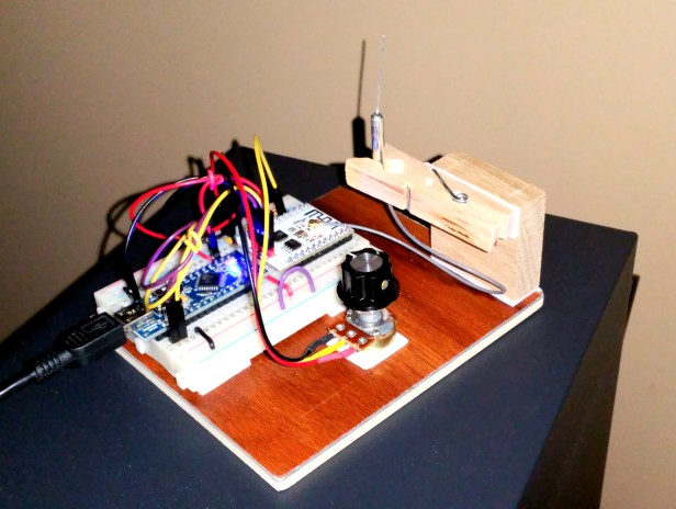
Experimenting with different antennas:

Best results with the external antenna (the metal one):
Experimenting with Deep Sleep:
In progress….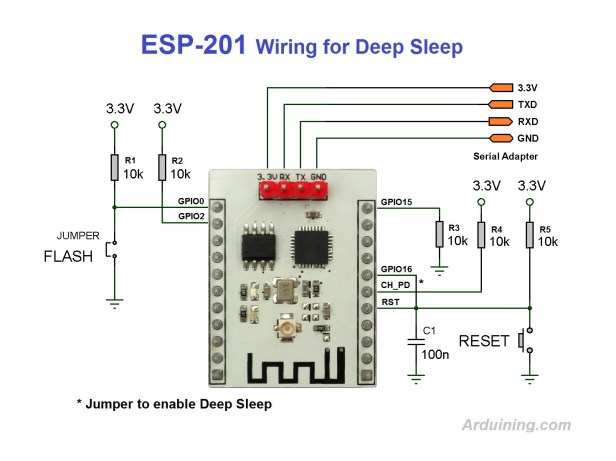


Thanks, that setup with DeepSleep works fine.
Hola amigo, gracias por tu aporte a la comunidad de los ESP8266, animado a comprar el modulo ESP-201, seguiré tu guía.
Consulta; Cual es la antena de metal, la que viene cuando compras el equipo, la delgada o la otra.
Recibe mis saludos desde Lima Perú.