

This exercise with the Arduino is inspired by the course:
Embedded Systems – Shape The World
Chapter : Finite State Machines
By Dr. Jon Valvano , professor in the Department of Electrical and Computer Engineering at The University of Texas.
http://users.ece.utexas.edu/~valvano/Volume1/E-Book/C10_FiniteStateMachines.htm
-The C code was adjusted to run in the Arduino UNO.
-Some changes were made in labels for better understanding.
-Most of the time was dedicated to make clear ilustrations and diagrams.
As the chapter explain, the Ojetive is:
Design a traffic light controller for the intersection of two equally busy one-way streets.
The goal is to maximize traffic flow, minimize waiting time at a red light, and avoid accidents.
Traffic light Controller using two sensors and 6 lights.
Two sensors detects the presence of cars in each direction.
Two traffic lights (Red,Yellow,Green) to control the traffic flow.
List heuristics describing how the traffic light is to operate:
-If no cars are coming, stay in a GREEN state. (which one doesn’t matter).
-To change from GREEN to RED, implement a YELLOW light of 0.5 seconds.
-GREEN lights will last at least 3 seconds.
-If cars are only coming in one direction, move to and stay GREEN in that direction.
-If cars are coming in both directions, cycle through all four states.
General System Diagram:

Definition of Inputs and Output:
Two Inputs from Switches detecting presence of cars in each direction.
Six Outputs to control the Lights ( RED, YELLOW, GREEN) in each direction.

Finite State Machine Transition Table
Four states are defined:
State O: goS Cars going in South Direction GREEN signal, West Direction with RED signal.
State 1: waitS Cars waiting in South Direction YELLOW signal, West Direction with RED signal.
State 2: goW Cars going in West Direction GREEN signal, South Direction with RED signal.
State 3: waitW Cars waiting in South Direction YELLOW signal, South Direction with RED signal.

Every state is described graphically in the following form:

The complete Finite State Machine Diagram:

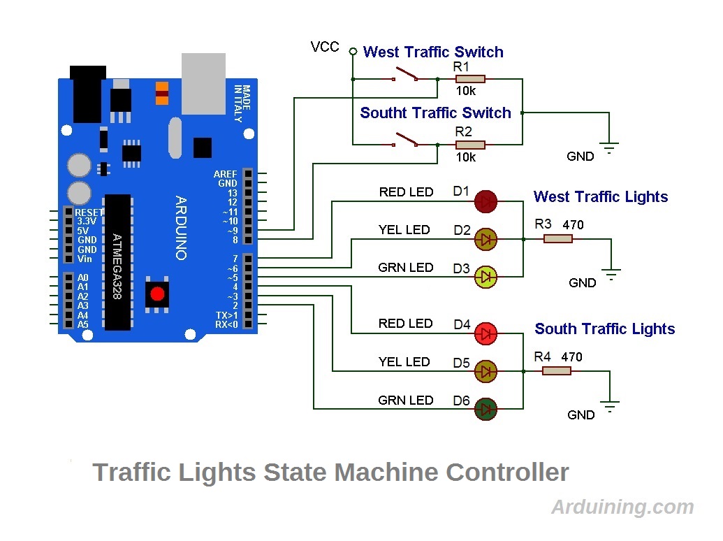
The wiring diagram with the Arduino UNO:
This is the Sketch :
/*Traffic_Light.ino        17 SEP 2015   Arduining.com
Implementing the traffic light controller using Finite State Machines modeling.
Using Direct Port Manipulation in the Arduino UNO.
Creating a Data Structure in C.
Port B pins 0 and 1 as inputs (Arduino pins 8 and 9):
Pin 8 = North Switch
Pin 9 = East Switch
Port D pins 2 to 7 as outputs (Arduino pins 2 to 7):
Pin 2 = North Red light
Pin 3 = North Yellow light
Pin 4 = North Green light
Pin 5 = East Red light
Pin 6 = East Yellow light
Pin 7 = East Green light
Based in: Finite State MachinesFrom:http://users.ece.utexas.edu/~valvano/Volume1/E-Book/
*/
#define SENSORS  PINB      // define the ATmega328 Port to read the switches
#define LIGHTS   PORTD     // define the ATmega328 Port to drive the lights
// Linked data structure
struct State {
  int Out;
  int Time;
  int Next[4];};
typedef const struct State STyp;
#define goS   0
#define waitS 1
#define goW   2
#define waitW 3
STyp FSM[4]={
 {0x21,3000,{goS,waitS,goS,waitS}},       //State 0 (goS)   go South.
 {0x22, 500,{goW,goW,goW,goW}},       //State 1 (waitS) wait South.
 {0x0C,3000,{goW,goW,waitW,waitW}},    //State 2 (goW)   go West.
 {0x14, 500,{goS,goS,goS,goS}}};        //State 3 (waitW) wait West.
int State;  // index to the current state
int Input;

void setup(){
  DDRB &= B11111100;  // Port B pins 0 and 1 as inputs (Arduino pins 8 and 9)
  DDRD |= B11111100;  // Port D pins 2 to 7 as outputs (Arduino pins 2 to 7)
}

void loop(){
    LIGHTS = (FSM[State].Out)<<2;    // set lights
    delay(FSM[State].Time);
    Input = SENSORS & B00000011;     // read sensors
    State = FSM[State].Next[Input];
}
Any comment to improve this presentation will be appreciated, thanks for visiting Arduining.com

very nicely done; great style
Great thanks!
How would the code be whithout using delay????