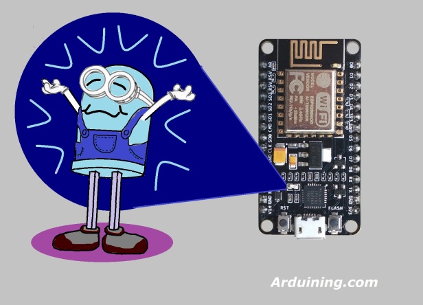
The first sketch used to test an Arduino compatible board is Blink.
After run Blink in my new NodeMCU Development Kit,
Started experiments with the WiFi connection:
-Mini servers to control leds, servos, etc..
-Send light intensity and temperature to ThingSpeak, Xively, Plotly etc..
-Serial data bridges
-etc.
The blue led in the board was used to signal the execution of a particular procedure.
Because the GPIO16 (DO) limitation to use the analogWrite() and looking to see my LED doing something else…
Inspired by the Apple’s “breathing” pattern used for the sleep indicator.
Here is the code to generate a “breathing LED”.
NOTE:
The Arduino code runs inside a multitasking application, the ESP8266 is running at the same time TCP and WiFi stacks.
The sketch can breake the multitasking execution if your code runs in a blocking section.
The delayMicroseconds() is one of those blocking functions, delay(0) was used to prevent watchdog reset inside the PWM loops.
/*LED_Breathing.ino Arduining.com  20 AUG 2015
Using NodeMCU Development Kit V1.0
Going beyond Blink sketch to see the blue LED breathing.
A PWM modulation is made in software because GPIO16 can't
be used with analogWrite().
*/

#define LED     D0        // Led in NodeMCU at pin GPIO16 (D0).

#define BRIGHT    350     //max led intensity (1-500)
#define INHALE    1250    //Inhalation time in milliseconds.
#define PULSE     INHALE*1000/BRIGHT
#define REST      1000    //Rest Between Inhalations.

//----- Setup function. ------------------------
void setup() {
  pinMode(LED, OUTPUT);   // LED pin as output.
}

//----- Loop routine. --------------------------
void loop() {
  //ramp increasing intensity, Inhalation:
  for (int i=1;i<BRIGHT;i++){
    digitalWrite(LED, LOW);          // turn the LED on.
    delayMicroseconds(i*10);         // wait
    digitalWrite(LED, HIGH);         // turn the LED off.
    delayMicroseconds(PULSE-i*10);   // wait
    delay(0);                        //to prevent watchdog firing.
  }
  //ramp decreasing intensity, Exhalation (half time):
  for (int i=BRIGHT-1;i>0;i--){
    digitalWrite(LED, LOW);          // turn the LED on.
    delayMicroseconds(i*10);          // wait
    digitalWrite(LED, HIGH);         // turn the LED off.
    delayMicroseconds(PULSE-i*10);  // wait
    i--;
    delay(0);                        //to prevent watchdog firing.
  }
  delay(REST);                       //take a rest...
}


I’m confused as this code does not compile in the Arduino ide. ‘D0’ was not declared in this scope. Am i doing something wrong?
Check if NodeMCU board is selected in Boards Manager…
Or change D0 to 16
I tried the 16 thing and while it compiled, nothing is flashing.
Can we use AnalogWrite() to generate PWM on NodeMCU pins????
Check this:
https://github.com/esp8266/Arduino/blob/master/doc/reference.md
They say: PWM may be used on pins 0 to 16
Thank you!
Fantastic!!
Didn’t work for me:
Arduino: 1.8.1 (Windows 7), Board: “Generic ESP8266 Module, 80 MHz, 40MHz, DIO, 115200, 4M (3M SPIFFS), nodemcu, Disabled, None”
…/LED_Breathing.ino.ino: In function ‘void setup()’:
LED_Breathing.ino:8: error: ‘D0’ was not declared in this scope
#define LED D0 // Led in NodeMCU at pin GPIO16 (D0).
^
…\LED_Breathing.ino.ino:17:11: note: in expansion of macro ‘LED’
pinMode(LED, OUTPUT); // LED pin as output.
^
…\LED_Breathing.ino.ino: In function ‘void loop()’:
LED_Breathing.ino:8: error: ‘D0’ was not declared in this scope
#define LED D0 // Led in NodeMCU at pin GPIO16 (D0).
^
…\LED_Breathing.ino.ino:24:18: note: in expansion of macro ‘LED’
digitalWrite(LED, LOW); // turn the LED on.
^
…\LED_Breathing.ino:8: error: ‘D0’ was not declared in this scope
#define LED D0 // Led in NodeMCU at pin GPIO16 (D0).
^
…\LED_Breathing.ino\LED_Breathing.ino.ino:32:18: note: in expansion of macro ‘LED’
digitalWrite(LED, LOW); // turn the LED on.
^
exit status 1
‘D0’ was not declared in this scope
————–
I am so close to trashing this unit as it is nearly impossible to work with.
Chris
I got this to work now. I found a site that had the pin constants defined.
Are you going to tell us what the correct pin mapping is?
The specific lines are below ardunaut’s reply.
Looks like the first line is missed:
#define LED D0
That wasn’t it. that define didn’t work for me. This is what I used:
static const uint8_t D0 = 16;
static const uint8_t D1 = 5; //ok
static const uint8_t D2 = 4; //ok
static const uint8_t D3 = 0;
static const uint8_t D4 = 2;
static const uint8_t D5 = 14; //ok
static const uint8_t D6 = 12; //ok
static const uint8_t D7 = 13;
static const uint8_t D8 = 15;
static const uint8_t D9 = 3;
static const uint8_t D10 = 1;
The “ok” are the connections I used to my 4 channel relay.
https://github.com/esp8266/Arduino/blob/master/variants/nodemcu/pins_arduino.h
In case anyone cares.
Does anyone know if this NODEMCU/Arudino IDE combo is based on the NoOS SDK or the RTS SDK? I couldn’t get anything to work with a network using the Arduino setup and I developed at the SDK level (RTOS). I got things working but I am having issues figuring out how to do GPIO on the RTOS SDK so I am thinking of porting my Ethernet working code over to Arduino.
I really need to know, is there a way to do this with micropython???
“D0” is predefined if you declare your board to be NodeMCU. You’ve declared a generic 8266
That’s wonderful indeed to get that effect. Simply amazing
What exactly represents BRIGHT? At first look it should represents the led luminosity.
But going deeper it represents only the number of step to reach the maximum luminosity.
Changing BRIGHT to 500 causes crash.