

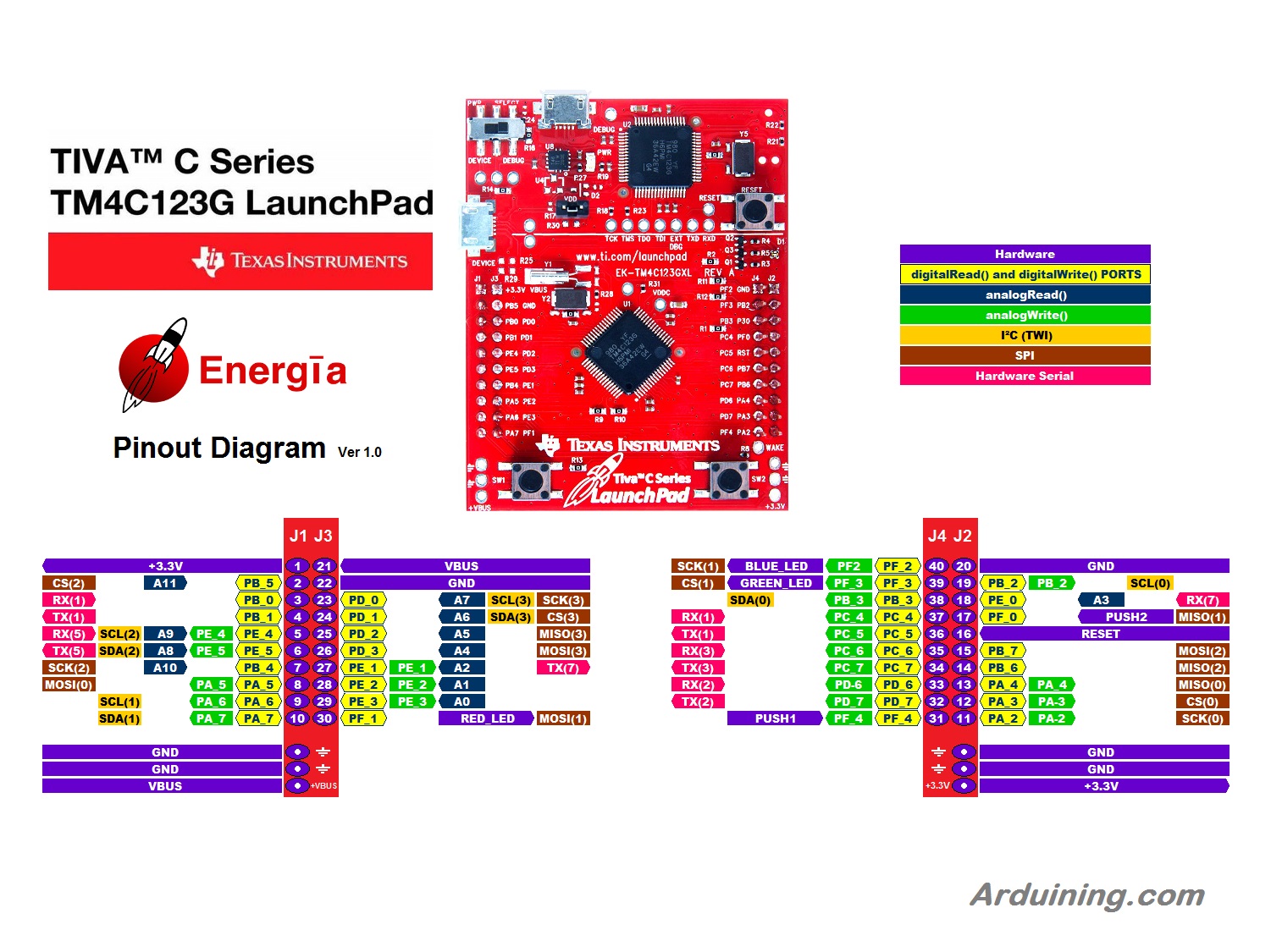
There are nice Energía diagrams for this LaunchPad in the Web.
Nevertheless, to become familiar with the board functionality and pin layout (and because enjoy drawing) decided to make a diagram. Tiva C Launchpad Pinout Diagram :
Since my first contact with Arduino always wanted to generate waveforms and see them in an oscilloscope. Almost three years ago made some projects with the MSP430 LaunchPad, can be seen at the SeuPay’s YouTube channel. Then also did some test with the Stellaris LaunchPad.
After more than a year with a couple of unboxed Tiva C LaunchPads, decided to try some waveforms generation with the inexpensive 32 bit, 80 MHz ARM platform. Using Energía, began some experiments with the Tiva C :
-Generating waves with the MCP4725, I2C 12-Bits DAC .
-Generating waves with the AD7801 Parallel 8-Bit DAC.
Direct Port Manipulation was used to reach higher data updates (samples/second).
Tiva C Launchpad and MCP4725
The first experiment generates wave shapes using an external DAC (Digital-To-Analog Converter).
The first choice was to use the MCP4725 from Adafruit’s (SparkFun also has a version with different address).

The following sketch fills an array with the values of a sine wave and feeds the DAC continuously with those values.
The “Fast Mode Write Command” of the MCP4725 is used.
/*MCP4725_Sin_01.ino   Arduining 17 APR 2015

-Energia Sketch to be used with Tiva C Launchpad and the Adafruit's MCP4725.
-I2C Fast Mode Write Command is used.
-120 samples are producing a 3.62Hz sine wave  => 434 samples/second.

Based in the code at:
http://electronics.stackexchange.com/questions/29457/how-to-make-arduino-do-high-speed-i2c

*/

#include <Wire.h>
#include <math.h>

//The MCP4725 from Adafruit:
//  I2C address is 0x62 ( by default A0 has a 10k pull-down resistor ).
//  I2C address is 0x63 if A0 is connected to VCC.
#define MCP4725_ADDR 0x62           //I2c address..

int ch[ 360 ] , cl[ 360 ];          //Arrays to load the sine wave.

//------------------------------------------------------------------------
void setup() {

  Wire.begin();           // SCL(3) and SDA(3) by default in Tiva C.
  Wire.setModule(0);      // Changing to SCL(0)and SDA(0),(PB_2 and PB_3).

  analogWrite(GREEN_LED,25);        //led 10% on.

// Create a sine table of 360 points:
  for ( int i = 0; i <= 360; i++ ) {
    int c = sin( i * 3.141592 / 180 ) * 2047 + 2048;
    ch[ i ] = int( c / 256 );      // the 4 most significant bits.
    cl[ i ] = c - ch[ i ] * 256;   // the 8 least significant bits.
  }
}

//------------------------------------------------------------------------
void loop() {
  for ( int i = 0; i < 360; i=i+3 ) {     //Only 120 points are used.
    Wire.beginTransmission(MCP4725_ADDR);
    //Fast Mode Write Command.
    Wire.write( ch[ i ] );        // the 4 most significant bits.
    Wire.write( cl[ i ] );        // the 8 least significant bits.
    Wire.endTransmission();
  }
}
This is the final result.

The DSO Nano is very handy because fits anywhere close to my desktop computer and
has become an excellent and inexpensive monitor for debugging.
DSO Nano screen capture of a simulated ECG wave (using the same hardware):

Working with C and Direct Registers (and Ports) Manipulation
Thanks to the page: http://users.ece.utexas.edu/~valvano/Volume1/E-Book/
Where the professor Valvano, from University of Texas at Austin, teach how to Develop Embedded Systems with the ARM M 4 Processor (Tiva C LaunchPad).
The chapters are mainly designed to work in C but, with some adjusts, the Energía environment does pretty good.
To enable Direct Register Manipulation we need to include in Energía the hardware register definitions.
Just write at the beginning of your code:
#include <tm4c123gh6pm.h>
This file is located in: C:\energia-0101E0015\hardware\lm4f\cores\lm4f\inc
I just made a copy and put it in: C:\energia-0101E0015\hardware\lm4f\libraries\tm4c123gh6pm
Notice that the file was copied inside a folder created with the same name.
(Surely there is a path to be included in Enegía to do this in a more elegant way).
Now you can use the Valvano’s examples in the Energía IDE, just remember to split the code appearing inside the main() function in two parts:
– The configuration code goes inside the setup() function of Energía.
– And the code running continuously is located inside the loop() function of Energía.
Is also possible to include Assembly code in Energía, but it needs another post.
Wiring the AD7801 8-Bits Parallel Digital to Analog Converter
A parallel DAC with 8 Bits is chosen to make the data transfer very fast.
Found the AD7801 at Mouser, the problem: (No DIP Package).
OK, let’s do some SMT work. With the DAC ordered and a 20 contact SOIC-to-DIP adapter.
…some SMT manual soldering…
A wiring diagram to connect the AD7801 to the Tiva C LaunchPad:

The AD7801, once soldered and wired, is very easy to operate. Simply put a new data in the PORTB and toggle PORTA bit 2 to produce a low pulse in the WR signal.
Did a A Quick-Ref of the chip:

Then I had to study Valvano’s code to understand how to deal with the Direct Register (and Ports) Manipulation.
First began to do the I/O Ports setup using the Direct Register manipulation, this part is not necessary, you can use Arduino code in Energía to do it. But was a good opportunity to learn some details of the the ARM Cortex M 4.
Finally, the code used to generate the fast data transfer between Tiva C launchpad and the AD7801:
/*AD7801_FastDAC.ino  Arduining.com 18 APR 2015

Testing the Tiva C LaunchPad and the AD7801 (Parallel Input 8-Bit DAC).
Using the PORTB to write the 8-Bit data.
Using PORTA bit 2 for the write signal (WR).

Results:
6 kHz    POINTS=256   ==>  1,536 Mega-samples/sec.
96 kHz   POINTS=16    ==>  1,536 Mega-samples/sec.
Note: faster if offset is a char.( 1,9 Mega-samples/sec.)
-----------------------------------------------------------------------------*/

#include  <tm4c123gh6pm.h>    // TM4C123GE6PM Register Definitions.
#include  <math.h>            // To calculate the sine table.

// bits 7-0 of port B address (Data).
#define ldata     (*((volatile unsigned long *)0x400053FC))
// bit 2 of port A address (WR signal).
#define wrsignal  (*((volatile unsigned long *)0x40004010))

#define POINTS    256    // Wave points.(256 max. to keep offset as char type)
#define PEAKVAL   128    // Wave Amplitud (128 max, inside 8-Bits range)
#define OFFSET    128    // Center of the wave (128 for full 8-Bits span).

int sintable[POINTS];    // Array to load the sin table data.
int offset=0;           // index to point the data inside sintable[].

//------------------------------------------------------------------------------
void setup(){

  PortB_Init();
  PortA_Init();

  // Fill the sin table with POINTS samples:
  for ( int i = 0; i <= POINTS; i++ ) {
    sintable[i] = sin( i * 3.141592 * 2 / POINTS ) * (PEAKVAL-1) + OFFSET ;
  }

}

void loop(){
    //Write data to the AD7801

    ldata= sintable[offset];        // Load value in the port B.
    wrsignal= 0;                    // WR signal to low.
    wrsignal= 4;                    // WR signal to high
    offset++;
    if((POINTS-offset)<=0)offset=0; // Keep offset in range.

  //  delayMicroseconds(2);           // To experiment different frequencies.
}

/*------------------------------------------------------------------------------
Subroutine to initialize port B all pins output.
Port B is used to output the data.
------------------------------------------------------------------------------*/
void PortB_Init(void){
  volatile unsigned long delay;
  SYSCTL_RCGC2_R |= 0x02;          // 1) activate Port B clock
  delay = SYSCTL_RCGC2_R;          // allow time for clock to stabilize
                                   // 2) no need to unlock PB7-0
  GPIO_PORTB_AMSEL_R &= ~0xFF;     // 3) disable analog functionality on PB7-0
  GPIO_PORTB_PCTL_R = 0x00000000;  // 4) configure PB7-0 as GPIO
  GPIO_PORTB_DIR_R |= 0xFF;        // 5) set PB7-0 as outputs
  GPIO_PORTB_AFSEL_R &= ~0xFF;     // 6) disable alt funct on PB7-0
  GPIO_PORTB_DR8R_R |= 0xFF;       // enable 8 mA drive on PB7-0
  GPIO_PORTB_DEN_R |= 0xFF;        // 7) enable digital I/O on PB7-0
}

/*------------------------------------------------------------------------------
Subroutine to initialize port A pin 2 as output.
PA2 is used to drive the WR signal of the DAC.
------------------------------------------------------------------------------*/
void PortA_Init(void){
  volatile unsigned long delay;
  SYSCTL_RCGC2_R |= 0x01;           // 1) activate clock for Port A
  delay = SYSCTL_RCGC2_R;           // allow time for clock to start
                                    // 2) no need to unlock PA2
  GPIO_PORTA_PCTL_R &= ~0x00000F00; // 3) regular GPIO
  GPIO_PORTA_AMSEL_R &= ~0x04;      // 4) disable analog function on PA2
  GPIO_PORTA_DIR_R |= 0x04;         // 5) set direction to output
  GPIO_PORTA_AFSEL_R &= ~0x04;      // 6) regular port function
  GPIO_PORTA_DEN_R |= 0x04;         // 7) enable digital port PA2
}
//End of code.
The complete assembly:

Two screenshots, thanks to the DSO Nano’s image capture function:
A 6 kHz sine wave using POINTS= 256
and a 95 kHz sine wave with POINTS= 16 .
The transfer speed is 1.536.000 samples/second.

Next steps:
Now we have a Sine Wave Generator, but the microcontroller is busy with this simple task.
If we need to do additional tasks like:
- Change the frequency and (or) the amplitude on the fly.
- Show those values in a display.
- Receive commands or transmit parameters serially.
We need to use interruptions…
Thanks for reading Arduining blog.

#define TCD_SH 0x01
#define TCD_CLK1 0x02
#define TCD_CLK2 0x04
#define TCD_BT 0x08
#define TCD_RS 0x10
void tcd1201d_setup()
{
DDRB = 0x1F;
}
unsigned char tcd1201d_out[1047];
int tcd1201d_dark;
void tcd1201d_read()
{
PORTB = TCD_SH | TCD_CLK1;
PORTB = TCD_CLK1;
for (int i = 0; i tcd1201d_dark) v = tcd1201d_dark;
v = (tcd1201d_dark – v) / 2;
if (v > 255) v = 255;
tcd1201d_out[i] = v;
}
}
void setup()
{
analogReference(DEFAULT);
tcd1201d_setup();
Serial.begin(115200);
}
void loop()
{
tcd1201d_read();
tcd1201d_read();
for (int i = 0; i < 1047; ++i)
{
Serial.print(tcd1201d_out[i], HEX);
}
Serial.println();
}
I do not understand register port, the above code Is it possible to convert your tm4c123