The idea of a camera using a single light detector always atracted my atention.
![]()
There are sophisticated applications using Compressive Imaging and single pixel cameras, but my objetive was more simple and easier to implement.
Inspired by the project “A Low-Cost Single-Pixel Thermographic Camera”.
Using the following material:
-Pan and Tilt servo assebly from ServoCity.com (A smaller one would be enough)
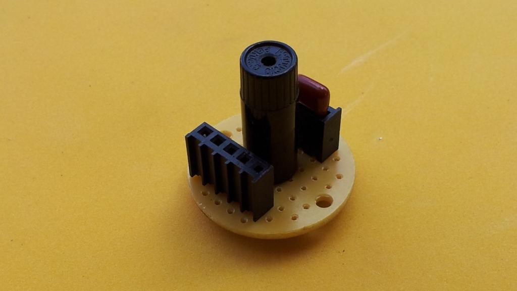
-TEPT4400 light sensor from VISHAY.
-Arduino NANO.
-120nF polyester capacitor
-Breadboars, jumpers etc..
At first, some experiments to sense very low light intensity (we will use a pinhole to catch a very small area of the image).

Using the Oscilloscope to observe the charge of the capacitor:

The following technic was implemented in the Arduino software:

This method is useful to increase the range of the light measured, but in this project only the gray area was used because the low light intensity and the short time to take the sample. Using a current amplifier to charge the capacitor may solve the problem (things to do).
The One Pixel Camera:

The full Assembly:
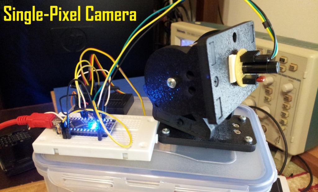
The Arduino Nano is reading the light intensity and controlling the servos, a separated breadboard is used to feed the servos with an external 5V power adapter.

The 40×30 pixels image is generated in Processing, the aplication is very simple. The Arduino sends x ,y coordinates and the the light intensity of each position , Processing just paint each point of the image using a square of 8×8 (screen pixels) with a grey value in the range 0-255.
Code to be used in Processing3 (Updated May 16,2021):
/* Pro3_Single_Pixel_01.pde Arduining MAR 16,2021 This Processing application plot the incoming value (0-255) in the specified coordinates with a gray scale 8x8 pixels square. The incoming characters at 9600 bauds have the following format: xPos,yPos,value CR xPos = x coordinate (1-40) yPos = y coordinate (1-30) value = gray scale value (0-255) CR ending with a carriage return character. */ import processing.serial.*; Serial port; int x; int y; int reading; String input; void setup(){ println(Serial.list()); // Check COM port list to edit the index in Serial.list()[] String portName = Serial.list()[4]; // <---- Edit the [index number here] port = new Serial(this, portName, 9600); port.bufferUntil(10); size(320,240); noStroke(); background(0); } void draw(){ if ( port.available() > 0) // If data is available, { input = port.readString(); // read incoming string and stored in input. input = trim(input); // removes spaces, carriage return, and tab characters. println(input); String[] vars = split(input, ","); x = int(vars[0]); y = int(vars[1]); reading = int(vars[2]); println("x: " + x + "\ty: " + y + "\tr: " + reading); int c = reading; fill(c); rect(x*8, y*8, 8, 8); } }And this is the sketch used in the Arduino, the macros for direct port manipulation can be avoided in the final version but was useful to experiment with the charge-discharge circuit.
/*Ard_SinglePixelCam.ino Arduining.com 06 JUL 2013 Sketch used in the YouTube video "Single Pixel Camera with Arduino" This code controls two servos to produce the scanning of the single pixel camera. The x and y position is sent with the corresponding light intensity. Characters are sent at 9600 bauds with the following format: xPos,yPos,value CR xPos = x coordinate (1-40) yPos = y coordinate (1-30) value = gray scale value (0-255) CR ending with a carriage return character. */ #include <Servo.h> #define TILT_SERVO 7 #define PAN_SERVO 8 #define H_SIZE 40 // Horizontal picture elements. #define V_SIZE 30 // Vertical picture elements. #define SENSOR 0 // Light intensity sensor. #define Xcenter 140 // X image center (Servo position in degrees) #define Ycenter 35 // Y image center (Servo position un degrees) //===================================================================== //Definitions and variables used by ReadPixel() funtion #define AnalogIn 0 #define Tcharge1 5000 //Delay microseconds before first Adquisition. #define Tcharge2 20000 //Delay microseconds before second Adquisition. //Macros to control the Light Sensor Circuit: #define Discharge {DDRD &= B00000011; DDRD |= B00001000; PORTD |= B00000000;} //D3 output LOW. #define Sense {DDRD &= B00000011; DDRD |= B00000000; PORTD |= B00000000;} //D3 as input. //Variables int first,second; //===================================================================== Servo servo_tilt; Servo servo_pan; //============== functions ============================================ //--------------------------------------------------------------------- void SendPixel(int xPos, int yPos, int value){ Serial.print(xPos); Serial.print(","); Serial.print(yPos); Serial.print(","); Serial.println(value); } //--------------------------------------------------------------------- void goto_origin(){ servo_tilt.write( V_SIZE/2 + Ycenter ); // Tilt servo at top. servo_pan.write( Xcenter - H_SIZE/2 ); // Pan servo to left. delay(1000); // time to reach origin. } //--------------------------------------------------------------------- int ReadPixel(){ Sense delayMicroseconds(Tcharge1); //Delay to take the first value. first= analogRead(AnalogIn); //first value is taken. delayMicroseconds(Tcharge2); //Delay to take the second value. second= analogRead(AnalogIn); //second value is taken. Discharge if (first<200)first= second; //if first is under 200, second will be under 1024. else first = first * 5 ; //if first is over 200, first*5 will be used. first = map(first, 0, 60, 0, 255); //map was adjusted for the light conditions. return first; } //=============== setup ================================================ void setup() { servo_tilt.attach(TILT_SERVO); servo_pan.attach(PAN_SERVO); Serial.begin(9600); ReadPixel(); //Read and discard it (Discharge for next read). } //================= main loop ========================================= void loop(){ goto_origin(); for (int y=0 ; y<V_SIZE ; y++) { servo_tilt.write(Ycenter + V_SIZE/2 -y ); delay(50); // time to reach position. for ( int x=0 ; x<H_SIZE ; x++) { // Scan from Left to Right. servo_pan.write(Xcenter - H_SIZE/2 + x); delay(50); // time to reach position. SendPixel(x, y, ReadPixel()); } y++; servo_tilt.write(Ycenter + V_SIZE/2 - y); delay(50); // time to reach position. for ( int x=H_SIZE-1 ; x>=0 ; x--) { // Scan from Right to Left. servo_pan.write(Xcenter - H_SIZE/2 + x); delay(50); // time to reach position. SendPixel(x, y, ReadPixel()); } } }Next steps:
-Increase the resolution and speed using stepper motors with gear reduction.
-Increase the sensibility and reduce the adquisition time using an Operational Amplifier as current amplifier in the charge circuit.
-Improve the resolution of the image using a smaller hole and a small box instead of a tube to capture the light (this is to eliminate the light reflections inside the cylinder).
-Hope to receive more ideas about this project, a well done Single Pixel Camera open the possibilities of experimenting with image processing algorithms.
The Youtube video shows the camera in action:

wow this is brilliant………May i see your sketches
Reviewing and commenting the code, I’ll post them during the weekend.
Great documentation of great Idea.
hello
this is really great I tried to replicate your project but cannot get any scanning information on the screen when running the sketch on processing, do you have any idea as to why this is happening, i am using a phototransistor from adafruit 2831 could this be the problem? thank you
Hello. The processing program does not work for me. Please, help. You will write a more detailed comment.
Run the Processing sketch once and check the com ports listed in the bottom, then replace portName in “port = new Serial(this, portName, 9600);” using your arduino port name. COM1, COM2, COM3, COM4 etc..
I can’t see the display of 8×8 pixels. They can appear sometimes. I changed the digital contrast but the scan track is not visible on the display. can you describe the program in more detail?
Check the values in the Serial Terminal or the Serial Plotter, use a flashlight to see the values changing. Check the sensor wiring. Use the TEPT4400 and 120nF.
The Processing Sketch was updated to run with Processing 3. This may be the real problem, I hope you can continue your project now.
your project suits me very much. I want to put a microwave sensor and get a radio telescope.